RV Backup Helper icon

Distance lines on the RV camera that never had any.

Your backup camera shows a picture and nothing else — no way to tell whether that post is four feet back or twelve. RV Backup Helper measures your vehicle from your camera once, then generates and flashes an Arduino sketch that draws those distances straight onto the live video.

Version 1.0.0 · Windows 10 and 11 · Python is bundled, nothing else to install · MIT licensed, no account, no telemetry

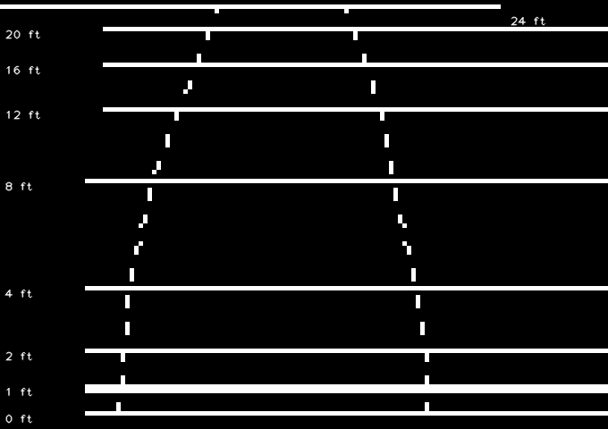
The overlay the shield draws: white horizontal lines labelled 0, 1, 2, 4, 8, 12, 16, 20 and 24 feet, each label set into a break in its own line, with a dashed pair of curves marking the width of the RV

Who this is for

Anyone who reverses something large using a camera that shows distance as well as a mirror does — which is to say, not at all.

RV and travel-trailer owners

The factory camera came with the coach and the factory display draws nothing on it. This adds the lines without replacing either, and without a trip to an installer.

Anyone backing onto a hitch

The last three feet are the ones that cost money. A 1 ft line, drawn heavier than the rest, is the difference between stopping and finding out.

Long overhangs and fifth wheels

A generic sticker-on guideline assumes a vehicle it has never seen. These lines come from a pole laid in your own driveway, behind your own bumper.

Installers and RV techs

One calibration per coach, saved as a small JSON file, regenerated into a sketch in one click. The measurement is the work; everything after it is repeatable.

Makers and Arduino people

An Uno, a Video Experimenter shield and about forty dollars of parts. The generated sketch is plain, commented C you can read, and the whole toolchain is in the repository.

Anyone who was quoted for a new head unit

Replacing a working display to gain guide lines is an expensive way to solve this. The camera and the screen you already own stay exactly where they are.

The lines are drawn in the wire, not in a computer

An RV backup camera is analogue composite video — the same signal television used before HDMI. That is unglamorous, and it is exactly why this works.

The principle

Slice the sync, add brightness, pass it on

Composite is a single wire carrying brightness and timing together. A chip can lock to that timing and inject extra brightness on top without understanding the picture at all. The trick is old: broadcast character generators did it for captions in the 1970s, and radio-controlled aircraft have used it for decades to put battery voltage over a live camera feed.

The alternative — digitise the video, draw on it, re-encode it — is easier to write and wrong for this job, because it puts a computer between the driver and the rear view.

RV camera ──▶ Video Input ─┤ shield ├─ Video Output ──▶ display Signal in, overlay mixed in, signal out. Nothing is decoded, buffered or re-encoded.

When it fails, it fails to nothing. The overlay adds no stage to the signal path. If the board dies, the camera passes straight through and the driver simply sees no lines — not a frozen frame, not a blank screen.

The measurement

Measured behind your bumper, not guessed from a template

A calibration is nothing more than a short list of correspondences between the real world and the picture: at 4 ft behind the bumper the ground appears on scan line 241, and the RV is as wide as the picture from column 437 to column 138.

The width corridor is drawn as a polyline through the points you marked rather than a straight taper, because a wide-angle lens bends what is really a straight path into a curve across the picture. Every extra distance you measure makes that curve truer.

The distance lines are deliberately not tapered to suggest perspective. That would imply a width nobody measured.

  • Six or seven distances is enough
  • Each point remembers its own video frame
  • Re-clicking corrects, it does not stack
  • The calibration is a 2 kB JSON file
  • The sketch is generated, never hand-edited

The overlay is monochrome, and that is hardware, not taste. It is one bit per pixel, and NTSC colour would need a subcarrier the microcontroller cannot generate while it is also locking to the camera. Line weight is therefore the only hierarchy available — which is why the 1 ft “about to touch something” line is drawn double.

What you need

Two pieces of hardware do the work in the vehicle, and one dongle borrows the camera onto a PC for an afternoon while you measure.

Part Why, and what to watch
Arduino Uno R3
or Duemilanove
Must be an ATmega328P. Not an Uno R4 — the video library is hand-written AVR assembly and will not run on the R4’s Renesas chip. Leonardo and Mega are out too. A clone works, but wants the CH340 driver installed before you leave for the campground.
Nootropic Design
Video Experimenter
shield
The overlay hardware itself. It sits on the Uno and carries the sync separator. Two settings on it — a SYNC SELECT jumper and an OUTPUT SELECT slide switch — must match the sketch you flash.
USB video capture dongle Any UVC composite grabber, to record the camera onto the PC for the calibration session. It is not needed once the board is flashed and in the vehicle.
RCA leads, and a long pole Composite is one signal wire and a ground. The pole is the measuring instrument: laid across the driveway at each distance, with the RV’s width marked on it.
A Windows PC Windows 10 or 11, for the calibration session and the upload. Nothing about the finished rig needs a computer — the board runs on its own in the vehicle.

Check the hardware before you buy the rest of it. Help → Check Hardware names the board by its USB id — so an Uno R4, a Leonardo or a Mega is caught by name rather than left to fail at upload — and says whether a capture device is present. It cannot see the shield, which is passive and enumerates nothing, and it cannot tell a composite camera from an AHD one. That last test still happens at the vehicle.

From a driveway to a grid, in ten steps

One afternoon, most of it spent walking a pole backwards and forwards. Steps 1 and 2 are on the bench, 3 to 4 are at the vehicle, and everything from 5 onwards happens at a desk with a recorded clip — so a misclick costs a click, not another trip outside.

On the bench

Put the shield in the camera’s video path

The shield sits inline exactly where you originally tapped the camera feed. For the calibration session the output goes to the USB grabber so the PC can record it; in the vehicle it goes to the display instead.

RV camera ──▶ Video Input ─┤ shield ├─ Video Output ──▶ display or USB grabber

Set the shield’s two controls for overlay use: the SYNC SELECT jumper on the two rightmost pins, so sync is taken from the incoming video, and OUTPUT SELECT on Overlay. Leave the small R4 pot fully counter-clockwise.

A torn or doubled overlay is not broken hardware. If a pattern appears but drifts, tears, or shows twice, the flashed sketch and the jumpers disagree — a free-running build slides against incoming video. Flashing the matching build fixes it with no wiring change at all.

On the bench

Prove the rig before you trust it

Flash arduino/rvbhBringUp/ first. It draws a border, three labelled reference rows and the current mode, so that any later problem is known to be in the calibration rather than in the rig.

Look for all four border edges — a missing side means the frame buffer is not the size the sketch thinks it is. And watch the on-board LED: a steady blink is the sketch reporting that it could not allocate its frame buffer, so nothing will ever be drawn. It blinks rather than failing silently, because the shield still passes video through and you would otherwise just see no grid and no reason.

Capture tab

Find your grabber

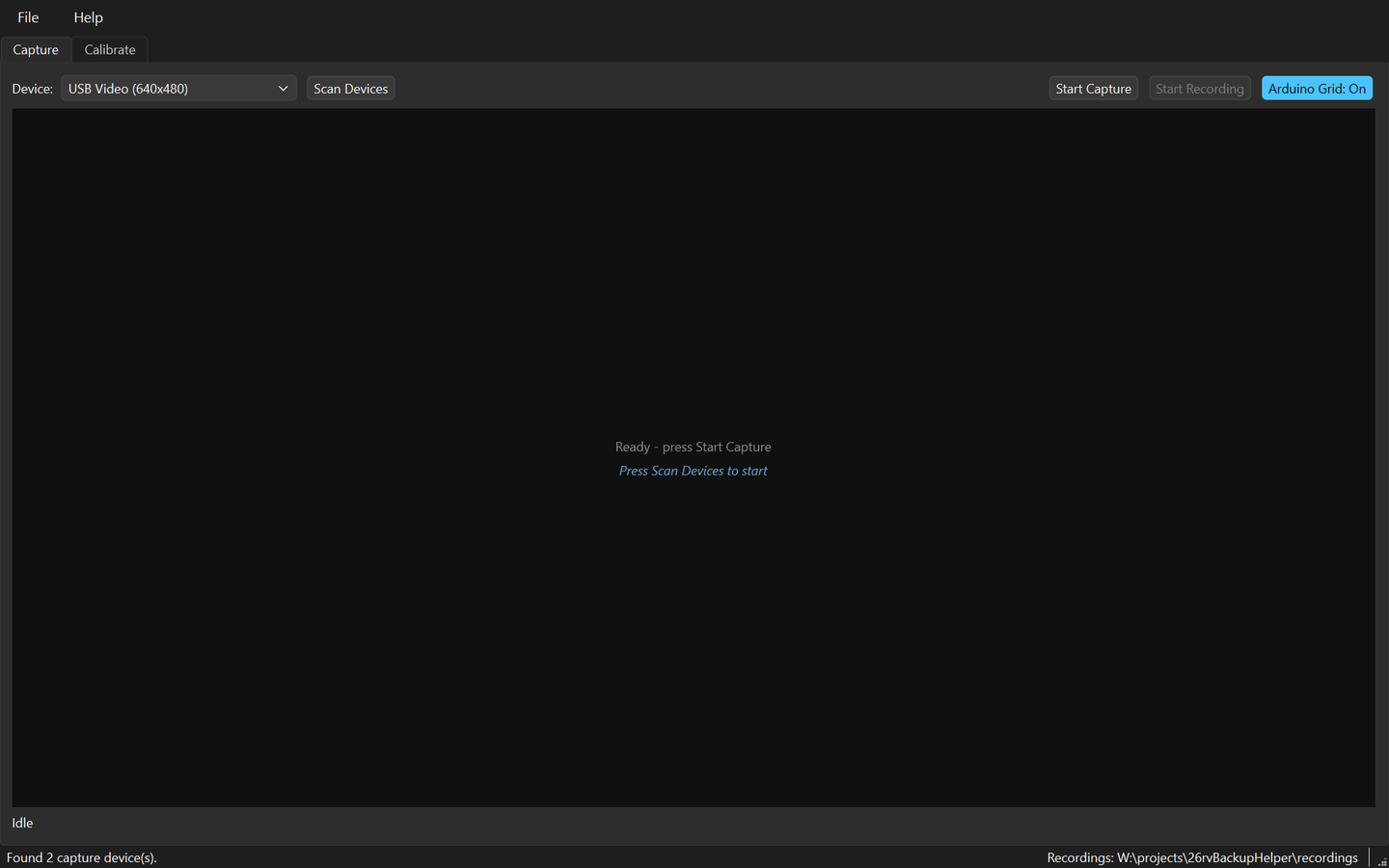
Press Scan Devices. Devices are listed by their Windows name, so the grabber is easy to tell from a webcam. The scan opens and closes each device in turn, so it takes a few seconds; it runs off the interface thread, so the window stays responsive.

A device that opens but is receiving nothing is listed as no video rather than hidden — hover it for the reason. Starting capture on one of those is fine and often correct: the preview says “Waiting for video signal” and begins the moment video arrives, which is exactly what an RV camera powered only in reverse gear needs.

Close OBS first. Only one application can hold a capture device at a time. With OBS on the grabber, RV Backup Helper opens the device and receives nothing — while the video is plainly visible in OBS, which makes it look like the app is broken.

The Capture tab after a scan, with USB Video (640x480) chosen in the device list and the status bar reading Found 2 capture device(s)
After the scan: the grabber picked by name, and the status bar counting what it found.
At the vehicle

Turn the grid off, then record

Arduino Grid: On / Off blanks the shield’s overlay so the camera passes through clean. Record calibration footage with it off — a grid burned into the clip sits directly on top of the pole markings you need to click afterwards. That mistake once cost a whole session.

Then lay a long pole across the driveway at each distance in turn, with the RV’s width marked on it, pausing a few seconds at each so there is a clean frame to find later. Six or seven distances is plenty. Every distance comes from its own frame, and the application records which.

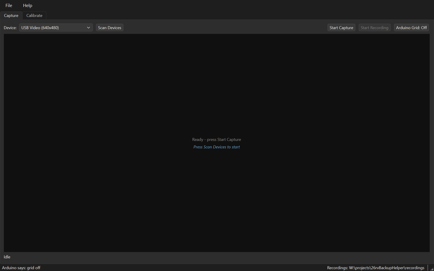
It takes a couple of seconds to answer, because opening a serial port resets the Arduino and the board has to boot first. The setting lives in the board’s own EEPROM, so it survives that reset, an unplug, and closing the application.

The Capture tab with the Arduino Grid button reading Off and the status bar reading Arduino says: grid off
The board acknowledging over serial: Arduino says: grid off.
Calibrate tab

Open the clip and step to a readable frame

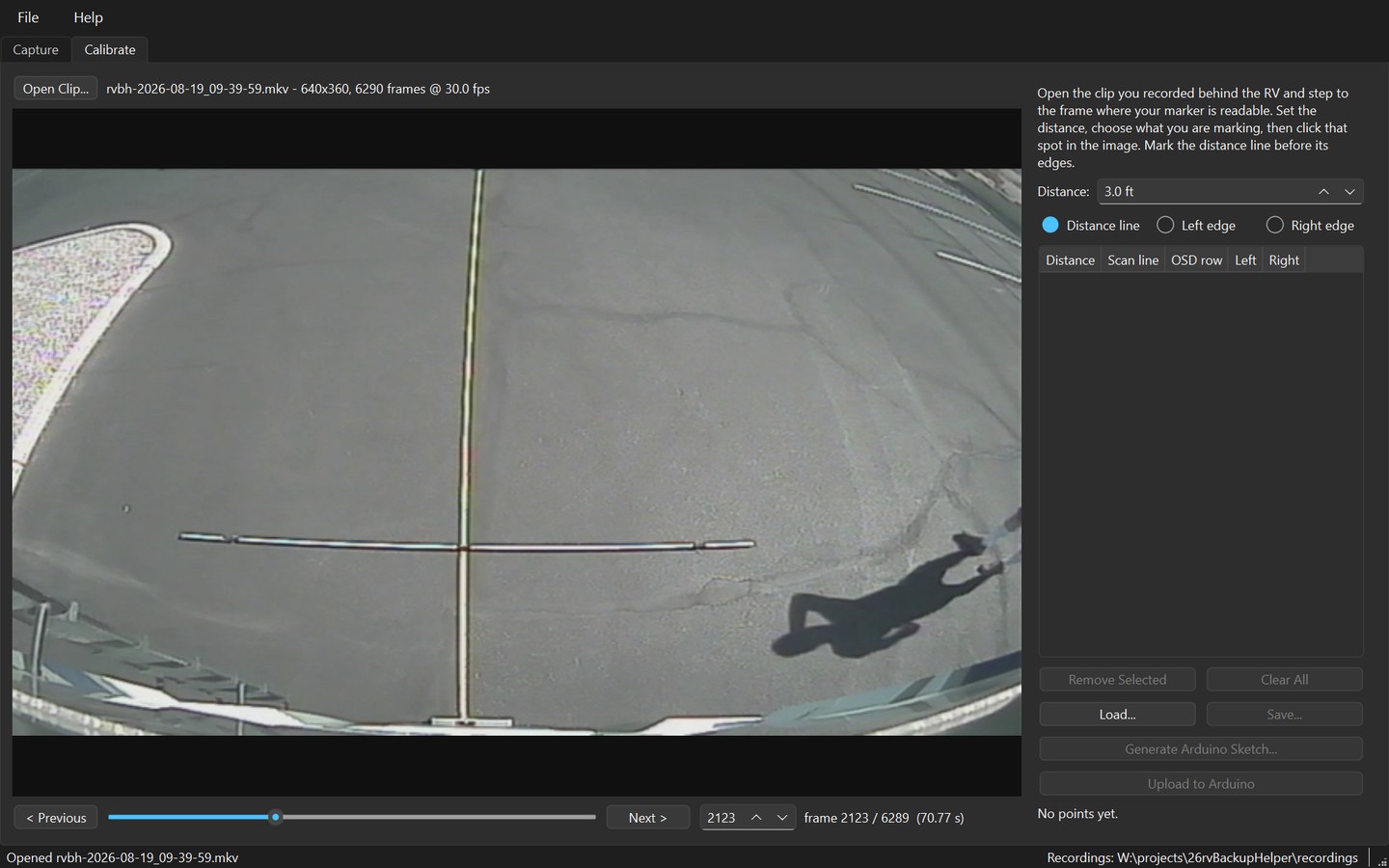
The left half is a clip browser — Open Clip…, the picture, and a transport with a slider, a frame box and Previous/Next. A clip you have just recorded is loaded here automatically.

Clips are MJPG-encoded, which compresses each frame on its own, so every frame decodes independently and stepping to an exact frame is exact. That matters more here than file size: a calibration measures one specific frame.

The cursor becomes a crosshair over the picture, because clicking the picture is how everything here is done.

The Calibrate tab with a clip open, showing the driveway behind the RV with a marked pole lying across it, and the transport controls beneath the picture
A clip open at frame 2123 of 6289, with the pole lying at the 4 ft position.
Calibrate tab

Click each distance, then the width marks

Set Distance to what this pole position represents, leave the radio button on Distance line, and click the pole in the picture. An amber guide is drawn where you clicked, so you can see at once whether it landed on the mark. Re-clicking the same distance replaces the earlier point rather than stacking two guides.

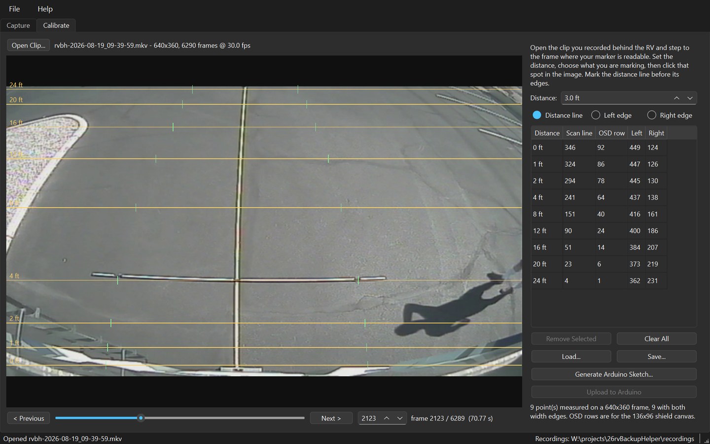
Then switch to Left edge or Right edge and click the width markings; a green tick shows where each landed. Mark the distance line before its edges — an edge with no line has nothing to attach to.

Step to the next frame and repeat. The table fills in as you go: the distance you typed, the scan line you clicked, the OSD row that rescales to on the shield’s 136×96 canvas, and the two width edges.

Maximise the window before marking. Clicks resolve to about a scan line and the picture is scaled to fit, so a bigger picture is a finer measurement. The summary underneath warns if two distances collapse onto the same OSD row — the capture is several times taller than the shield’s canvas, and the hardware cannot draw them apart.

A finished calibration: amber guide lines labelled 0 to 24 feet across the picture, green width ticks on each, and a filled table listing distance, scan line, OSD row and both edges
Nine points measured, all nine with both width edges — amber for the distance lines, green for the edges.
Calibrate tab

Save the calibration

Save… writes a small JSON file. Of the three things this process produces, it is the only one that matters: the clip is large and disposable, the sketch is generated in one click, and this cannot be reproduced without another trip to the RV.

{ "version": 1, "sourceClip": "2026-08-19_09-39-59.mkv", "frameWidth": 640, "frameHeight": 360, "points": [ { "distanceFeet": 4.0, "scanLine": 241, "frameIndex": 2123, "overlayRow": 64, "leftEdge": 437, "overlayLeft": 93, "rightEdge": 138, "overlayRight": 29 } ] }

The scan line is stored with the frame height it was measured against, because a scan line means nothing without knowing what height it came from. Opening a clip of a different frame size therefore clears the points, deliberately: silently mixing the two would produce a calibration that looks fine and is wrong.

Calibrate tab

Generate the Arduino sketch

Generate Arduino Sketch… turns the measurements into C. Each row carries the scan line and the frame it came from, so a line that looks wrong on the vehicle can be traced back to the moment it was measured.

const GridLine GRID[] PROGMEM = { { 92, 1, 1, 89, 16, gridLabel0 }, // 0 ft, scan line 346 of 360, frame 441 { 86, 2, 1, 83, 16, gridLabel1 }, // 1 ft, scan line 324 of 360, frame 1001 <- emphasised { 78, 1, 1, 75, 16, gridLabel2 }, // 2 ft, scan line 294 of 360, frame 1642

The header carries the rest of the provenance — source clip, capture size, timestamp, board, library and jumper requirements — so the file stands on its own if it is ever opened away from the project. Versioning by name works well, because the calibration each sketch was built from is committed alongside it.

Never hand-edit a generated sketch. Regenerating from the JSON is one click, and the file says GENERATED FILE at the top for a reason. Tables and labels live in flash rather than RAM, which is not tidiness: the video frame buffer takes 1632 of the Uno’s 2048 bytes at run time, and keeping the tables out of RAM is what leaves enough stack to run at all.

Calibrate tab

Upload it to the board

Upload to Arduino compiles and flashes with arduino-cli — exactly what the IDE’s upload button does. The Arduino IDE is never required. It takes a few seconds and reports the board’s own size summary when it finishes, so you see what actually landed rather than an assumption.

Uploaded to COM3. Sketch uses 7978 bytes (24%) of program storage space.

It offers the last sketch you generated, remembered between sessions, so a sketch saved under its own name is still what Upload flashes after a restart. Help → Check Toolchain answers the same question with no board attached, by compiling something and reporting which arduino-cli, data directory and libraries it used — the compile is the point, because every check short of building something once insisted a missing AVR core was installed.

Back in the RV

Turn the grid back on

Arduino Grid → On. If you blanked the overlay to record calibration footage, it is still blanked — and the setting lives in the board’s EEPROM, so it survives everything, including a reflash of the same sketch.

Move the shield’s output back to the display, and that is the job done. Horizontal lines mark your measured distances, each label set into a break in its own line so there is no doubt which belongs to which. The dashed pair is the width of your RV, drawn through the points you marked. The 1 ft line is heavier: it is the “about to touch something” line.

Nothing needs a computer from here on. The board runs on its own, and the camera passes through it whether or not the sketch is doing anything.

The finished overlay: white horizontal lines labelled 0, 1, 2, 4, 8, 12, 16, 20 and 24 feet, with a dashed curved pair marking the RV's width and a heavier line at 1 foot
The overlay buffer the shield draws, rendered from the tables in a generated sketch.

What it will not do

Worth reading before you buy a shield, rather than after.

It cannot skip the measuring. There is no template, no vehicle database and no guess: the lines exist because you laid a pole behind your own bumper and clicked it. That is an afternoon, once, and it is the whole reason the result is worth trusting.

It is not a proximity sensor and not a warning system. It draws where the ground was when you measured it, on flat ground. A slope, a kerb, or something hanging above the ground is not what the lines describe. It is a better rear view, not a substitute for using it.

The application runs on Windows 10 and 11, because finding and opening capture devices by name goes through DirectShow. The board and the shield, once flashed, have nothing to do with any operating system.

Download RV Backup Helper 1.0.0

Free. No account, no ads, no telemetry, and the only network call the application ever makes is checking whether the published manual is reachable before it opens it.

Windows 10 and 11

Installer

rvBackupHelperSetup-1.0.0.exe, about 67 MB. Python is bundled, so there is no prerequisite of any kind. The install is per-user: no UAC prompt, and nothing lands in Program Files.

The wizard runs the hardware check on the page after Welcome, before a single file is written, so somebody with no grabber finds out in five seconds rather than after a download. The 295 MB Arduino AVR core is a tick box at the end, and only uploading needs it.

Download for Windows
From source

Clone and run

What you want if you intend to change the code. Python 3.14 or newer, then one command sets up the Arduino toolchain and proves it by compiling the real sketch.

git clone https://github.com/Charette-AI-Group/rvBackupHelper.git cd rvBackupHelper python -m venv .venv .venv\Scripts\python.exe -m pip install -e ".[dev]" .venv\Scripts\python.exe tools\setupToolchain.py

The TVout fork the shield needs is committed in arduino/libraries — there is nothing to install and no wrong version to install by mistake.

View the source

The installer is not code-signed. Windows shows a SmartScreen warning the first time — choose More info, then Run anyway. Signing certificates cost money every year, and this is free software. If you would rather not take that on faith, the from-source route above builds the same application out of the same repository.

Documentation

The walkthrough above is the short version. The manual is five pages with the screenshots, the traps, and the reasoning behind the awkward decisions — and F1 in the application opens it.

At the vehicle

What to take, and the order to do it in, on one page.

Source code

All of it, MIT licensed — including the sketch generator and the vendored video library, which carries its own MIT licence beside it.

The hardware

Neither of these is ours; both are worth reading before ordering.

More from Charette AI Group

Free desktop tools built the same way.